

A commercial greenhouse controls design framework for independent lighting zones serving beds with different crops, daylight, and operational requirements. Start from project inputs, keep model assumptions traceable, and verify crop-level performance before commercial acceptance.
Key Takeaways
- A greenhouse lighting decision starts with the crop canopy, not a generic fixture count.
- Natural-light contribution, controls and geometry must be written as testable assumptions.
- Simulation outputs are preliminary until verified against installed equipment.
- Document acceptance criteria before purchase and record as-built evidence.
This guide explains greenhouse lighting control zones for commercial growers, greenhouse builders, research facilities and lighting-system integrators. It focuses on engineering choices, realistic constraints and evidence that can be inspected before a purchase commitment. The intended reader is planning a real project, not comparing decorative indoor lamps.
For the broader system context, consult our greenhouse supplemental lighting framework, the engineering design inputs checklist and lighting schedule optimization discussion. The choices below must be reviewed against local electrical rules, the specific crop and the equipment data actually supplied.
Define zones around decisions rather than fixture rows
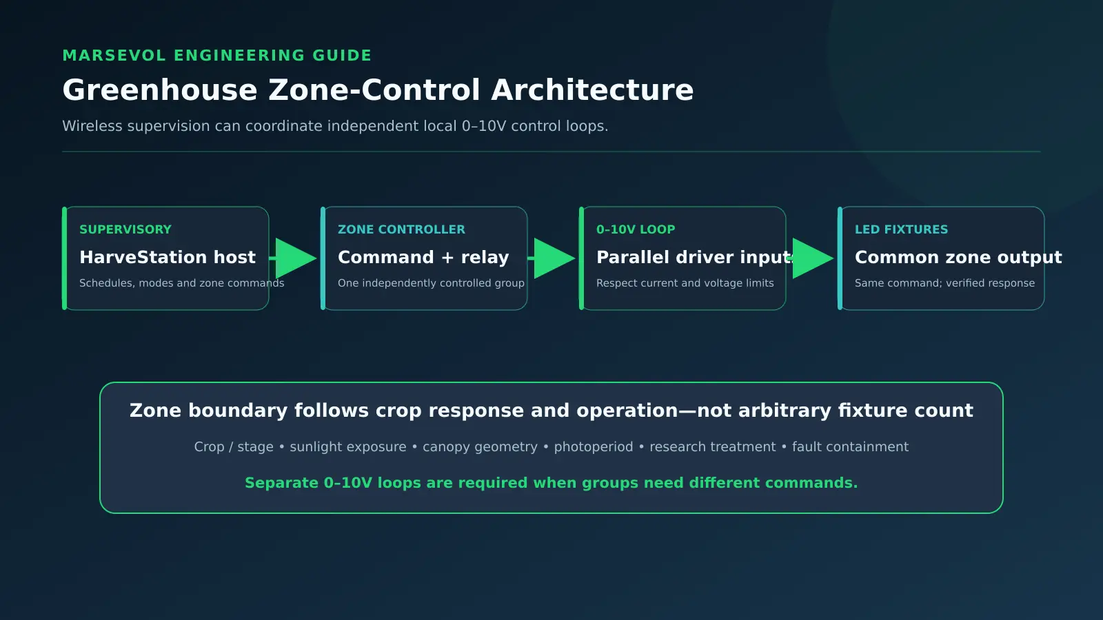
A control zone is useful only if the fixtures within it should respond to the same crop requirement and operating constraints. Raised-bed houses can contain leafy crops, propagation modules, herbs and fruiting plants with different heights, target DLI and harvest schedules. One long electrical circuit is therefore not automatically one agronomic zone. Start with a floor plan that shows individual beds, crop assignments, sunlight exposure, fixture groups and available driver interfaces.
Define the decision owner for each candidate zone. Some beds can share a lighting recipe if canopy conditions and crop targets are sufficiently similar; others need separate dimming even when mounted side by side. Mark transition areas, buffer fixtures and overlap from neighboring zones. This prevents independent commands from being undermined by uncontrolled cross-light. A design with fewer well-chosen zones can outperform a nominally sophisticated system whose zones cannot be verified in the field.
Separate the lighting objective from the electrical topology
Physical cable circuits, communication addresses, crop zones and control groups solve different problems. Two beds may share electrical protection while accepting separate dimming signals, provided the equipment and code allow it. Conversely, a large independently switched circuit may be unacceptable if parts of the crop require different intensity. Produce four aligned diagrams: bed and crop map, fixture grouping, power distribution and control communications. Reconcile their identifiers so technicians do not have to infer a zone from an ambiguous cable label.
For each zone list connected fixtures, nominal power, expected drive range, control protocol, sensor source, recipe owner and fault response. If a multi-fixture driver is involved, document exactly which channels can be controlled independently. Avoid promises of per-fixture tuning unless the selected hardware supports it. The system acceptance criteria should refer to real hardware capabilities rather than merely to a software dashboard demonstration.
Build DLI feedback from trustworthy inputs
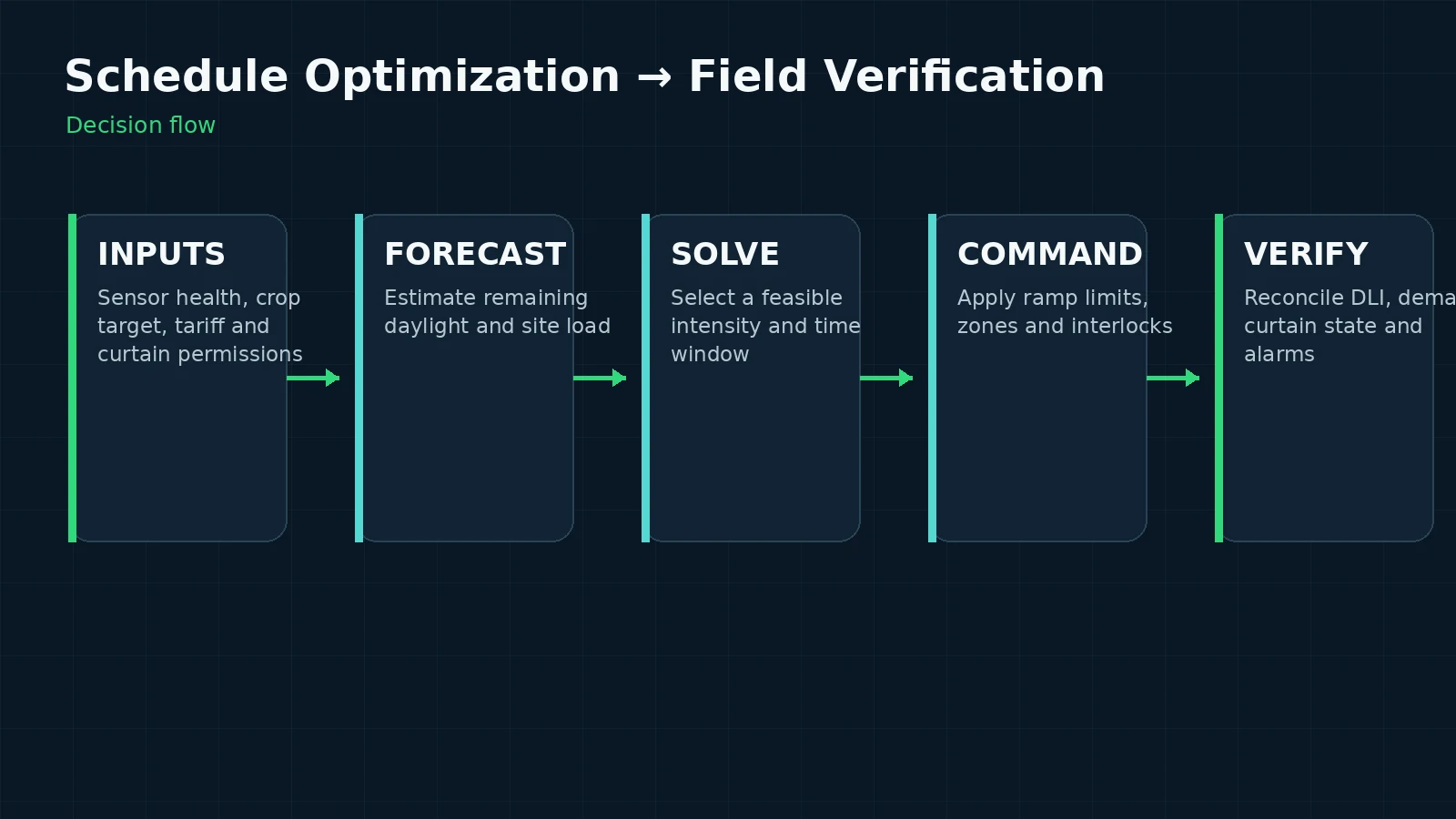
Closed-loop DLI operation requires an estimate of photons already delivered and a transparent target for photons still needed. Record whether sensors are mounted outdoors, under glazing or at the crop canopy. An outside irradiance sensor alone does not measure the effects of roof transmission, shading curtains and bed-level obstructions; a transfer model and calibration plan are needed. If canopy sensors are shared by multiple zones, show why the selected sensor position represents them.
A practical control cycle records sunlight contribution, electric-light contribution, remaining operating hours and permitted dimming range. The controller can then select a feasible response while respecting photoperiod, curtain and climate limits. Sensor errors and missing data must have explicit fallback behavior, for example a preapproved conservative time schedule, rather than uncontrolled maximum output. The control specification should explain what happens after a power interruption or a device clock reset.
Avoid false equivalence between DLI and crop performance
Delivering the same calculated DLI in two zones does not guarantee equal growth. Crop response depends on intensity distribution, photoperiod, temperature, stage, spectrum and how uniformly light is spread across leaves. Independent zones make it possible to test alternative recipes, but they also require recordkeeping: changes in crop cultivar or climate conditions can confound an otherwise convincing lighting comparison.
Define what the grower is actually optimizing: harvest timing, morphology, fresh weight, fruiting productivity, quality or stability through winter. Build recipes around documented crop evidence and a measured trial when uncertainty is high. Do not promise universal PPFD values for raised-bed systems; the same bed dimensions can host crops whose biological demands differ substantially.
Dimming interfaces and device compatibility
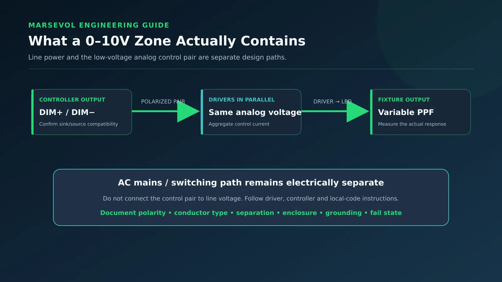
Before procurement, verify the chosen driver’s dimming behavior and the controller’s supported output. The expression 0–10 V can hide implementation details such as minimum light output, driver off state, linearity, isolation, wiring limits and what happens when the control wire is disconnected. Digital control protocols introduce address management, gateway compatibility and recovery behavior. These details must be agreed with the integrator; they cannot be corrected by writing a better software schedule alone.
Create a simple interface table listing each fixture group, driver model, controller port, expected output range, feedback capability and communication failure mode. Test at representative commands such as low, medium and full permitted output with a meter and fixture measurements. Check inrush, power factor and current draw if relevant to the electrical design. A control system that displays 50 percent may not produce half the photon output.
Coordination with curtains, ventilation and climate
In commercial greenhouses, light management is not isolated from the rest of environmental control. Curtain position alters transmitted solar radiation and may change thermal conditions; ventilation affects fixture clearances and electrical exposure; humidity and condensation can affect equipment reliability. If a local light-abatement rule applies, lighting commands must honor its constraints even when DLI targets are unmet.
Model a permission hierarchy before automation: safety and statutory constraints first, crop operating limits second, and electricity-cost optimization third. Establish ownership of the interface between lighting and climate controllers. Specify whether curtain sensors are hardwired, networked or inferred, and how the system behaves when their state is unknown. Every cross-system interlock must have a witnessed commissioning test rather than an assumption of interoperability.
Multiple-zone scale and network reliability
Large houses may contain hundreds of fixtures and many zones. Network loading, address limits, cable lengths, controller memory and sensor update frequency all need to be considered before a product is chosen. Document the maximum practical number of independently commanded groups, not simply the advertised number of fixture addresses. Expansion can fail if zone identifiers cannot be moved cleanly from a design drawing into control software.
Provide a naming convention aligned to greenhouse section, bed, circuit and zone. Keep revision history for recipes, controller firmware and commissioning changes. When the system loses cloud access or local network communications, define which controls continue operating and which adjustments are suspended. Local autonomy, secure accounts and role-based permissions matter for a growing operation that cannot tolerate a failed marketing dashboard or remote service disconnecting its lights.
Validate delivered light, not just command outputs
A valid commissioning process compares controller commands with the physical result at the crop. Log the intended zone setpoint, actual electrical or driver response, measured PPFD at representative positions and the conditions affecting natural light. Test neighboring-zone influence by turning one group on and off in a controlled sequence where safe. Without such tests, a logically correct control map may still over-light one aisle and leave the edge of a bed below the intended target.
Use a repeatable acceptance matrix with each zone’s normal mode, override mode, sensor-disconnected condition, communications loss, curtain change and recovery after power failure. Confirm that operators can identify alarms and restore safe service. Calibration dates and sensor cleaning procedures should appear in the operations handover. A successful dashboard screenshot is not an acceptance record.
Operations and future optimization
After commissioning, review weekly logs against target DLI, delivered electric contribution and energy consumed. Look for systematic under-delivery under poor winter daylight, simultaneous peaks at expensive tariff periods or zones that consistently operate at their limits. Interpret any apparent crop benefit alongside temperature, irrigation and seasonal conditions so the lighting system does not receive credit for unrelated changes.
Begin optimization with low-risk measurements and recipe adjustments, not automatic global increases in output. The most valuable improvement may be a better sensor position, a corrected fixture group or a shortened response delay. Establish change approval for recipes affecting yield-critical crops, and retain previous working settings for rollback. This closes the loop between initial zone design and a maintainable commercial greenhouse system.
Calculation and assumptions
Use average PPFD over the specified canopy plane; this relation does not account for variations in sunlight, output calibration, spectral response, canopy growth or zone overlap. Record all those conditions separately.
Buyer verification checklist
Before approving a quotation, request the site and crop design basis; a scaled drawing with actual planted areas and mounting heights; the exact luminaire data and control protocol; a calculation table with source files; a differentiated analysis of daylight and electric light; the required electrical and structural interfaces; and an acceptance plan with measurable test steps. Record the author, revision date and assumptions of each deliverable so procurement, installation and operations refer to the same approved version.
Ask the supplier to identify unresolved parameters rather than replace unknown information with unmarked defaults. For an early-stage project, separate confirmed requirements from provisional assumptions and describe who must verify each item. A small pilot or bench-level test can be useful, but only if its geometry, light conditions, crop stage and measurement method are sufficiently representative of the larger project.
FAQ
Can I reuse a fixture layout from another greenhouse?
Not without checking dimensions, crop canopy, glazing, suspension, solar climate and intended operating schedule. Reusing a framework is efficient; reusing an unverified map can be expensive.
Is PPFD or DLI more important?
Both are required for many supplemental-lighting decisions. PPFD describes photon rate at the canopy and DLI its integrated daily quantity; distribution and crop response matter too.
Does a higher nameplate output always improve the project?
No. The relevant decision is delivered light over the planted area under real constraints, alongside installation, energy, controls and maintenance costs.
Conclusion
greenhouse lighting control zones should produce a documented design decision, not only a product list. Tie the crop goal and calculated light requirement to measured geometry, independent operating constraints, traceable fixture data and a clear acceptance procedure. For a site-specific plan, share bed dimensions, crop stage, location, target DLI or PPFD basis and representative greenhouse photographs through MarsEVOL Solutions. The next useful step is a reviewed engineering layout rather than a generic lighting promise.
Build a Project-Specific Lighting Plan
Send MarsEVOL your bed layout, crop stages, zone boundaries, canopy and mounting heights, lighting targets, available circuits, dimming interface and sensor positions. These inputs support a reviewable preliminary lighting and control plan.
Explore More MarsEVOL Resources
Review engineering design inputs and glazing transmission analysis to define crop and natural-light assumptions before requesting a layout.
Use lighting schedule optimization, official lighting resources and electricity tariff analysis to connect control choices with rates, official resources and implementation constraints.
References
- Cornell University. Controlled Environment Agriculture. Institutional resource entry point.
- Michigan State University. Floriculture. Institutional resource entry point.
- U.S. Department of Energy. Solid-State Lighting. Institutional resource entry point.
These are institutional resource entry points, not project-specific endorsements or proof of a particular numerical crop recipe. Verify the latest technical publications and local requirements before design approval.