
Quick Answer
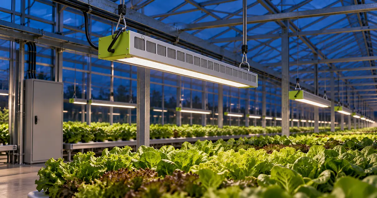
Greenhouse lighting electrical design connects a verified fixture schedule to the actual supply, protected circuits, compatible controls and safe maintenance arrangements. Calculate AC input current using the selected driver’s voltage and power factor, then check continuous loading, startup behavior, cable routes and environmental suitability. A crop-control zone is not automatically one electrical circuit, and dimming is not electrical isolation.
Key Takeaways
- Confirm supply voltage, phase configuration and available capacity before ordering drivers.
- Separate running current, startup inrush and control-loop capacity; each can impose a different limit.
- Use exact model documentation, not a product-family voltage range or an IP label alone.
- Agree circuit-to-zone mapping, restart behavior and commissioning records before installation.
A good greenhouse lighting electrical design begins after the light requirement is defined, but before equipment is purchased. The supplemental-lighting design guide explains the crop objective; this article addresses the electrical handoff for commercial growers, integrators and research facilities.
Scope: This is a planning guide, not a wiring instruction or a construction-ready design. A qualified electrical designer and licensed installer must apply the locally adopted code, equipment instructions and authority-having-jurisdiction requirements. U.S. references below do not replace Canadian provincial requirements or local amendments.
1. What Supply Information Does Greenhouse Lighting Electrical Design Need?
Record the actual service and the proposed fixture connection voltage. A description such as “three-phase power available” is insufficient. Distinguish line-to-line voltage from line-to-neutral voltage, and identify the intended driver variant.
Request the latest single-line drawing, panel schedule, spare capacity assessment, frequency, grounding arrangement and available fault-current information. Add other coincident loads: pumps, ventilation, heating, cooling and future expansion. Empty panel spaces do not prove that a service or transformer has spare capacity.
Ask the electrician to identify installation constraints without requiring growers to open electrical equipment. Record the jurisdiction and applicable code edition in the design brief. OSHA’s equipment provisions address ratings, fault interruption and installation instructions, but they are not a substitute for a project electrical design. [1]
2. What Belongs in the Fixture Load Schedule?
Use a revision-controlled schedule for the exact luminaires and drivers being supplied. Connect every fixture identifier to the approved lighting layout, then record:
| Required field | Why it matters |
|---|---|
| Model, driver and quantity | Prevents substitutions from silently changing the electrical load. |
| AC input watts, voltage and current | Defines the supply-side load, not LED-module output power. |
| Power factor and test conditions | Supports preliminary current estimates at the relevant operating point. |
| Inrush peak, duration and switching data | Supports startup and protective-device compatibility review. |
| Dimming, leakage and environmental data | Identifies interface, protection and installation constraints. |
Include controllers and other auxiliary loads separately. A luminaire’s AC input rating already includes its driver losses; do not divide that rating by driver efficiency again. If only LED output power is supplied, obtain the complete luminaire input data.
For an LED-for-HPS retrofit, have the installer reassess existing circuits, switching equipment and connections. Lower running watts do not establish that the new electronic load is compatible.
3. How Do You Calculate LED Grow Light Input Current?
For a single-phase load, divide real AC input power by RMS voltage and true power factor. Prefer the manufacturer’s declared input-current data for final design, including its voltage, temperature and tolerance conditions.
Single-phase AC input
I = Pinput ÷ (VRMS × PF)
I: amperes; P: real input watts; V: supply volts at the driver; PF: dimensionless true power factor, not photon efficacy or driver efficiency.
Worked example: 24 hypothetical luminaires
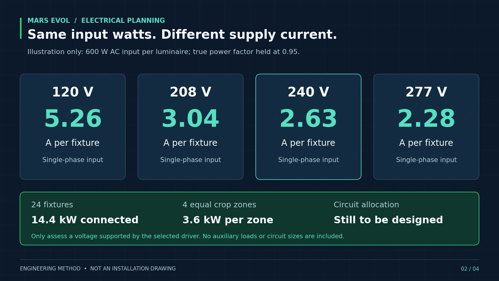
Assume 24 luminaires, each drawing 600 W AC at full output, with PF of 0.95 at 240 V. These are teaching assumptions, not SOLIFY specifications, a customer installation or an approved circuit arrangement.
Illustrative load calculation
Per fixture: 600 ÷ (240 × 0.95) = 2.63 A
Connected lighting power: 24 × 600 ÷ 1,000 = 14.4 kW
Four equal crop zones: 6 × 600 ÷ 1,000 = 3.6 kW per zone
Auxiliary loads are excluded. Crop zones are operational groups; this calculation does not assign fixtures to branch circuits.
Ignoring PF would give 2.50 A per fixture, understating this assumed current. At unchanged input watts and PF, a lower supply voltage produces higher current. The comparison below applies only to a driver approved for the voltage shown; it is not permission to reconnect a fixture to another supply.
Do not sum currents from different phases as though they were one conductor. Three-phase feeder assessment requires the actual connection scheme, phase allocation and imbalance review. Likewise, a full-output PF assumption should not be carried into deep-dimming calculations without evidence. MEAN WELL documents load-dependent PF behavior in its LED-driver technical FAQ. [2]
4. How Many Fixtures Can One Circuit Supply?
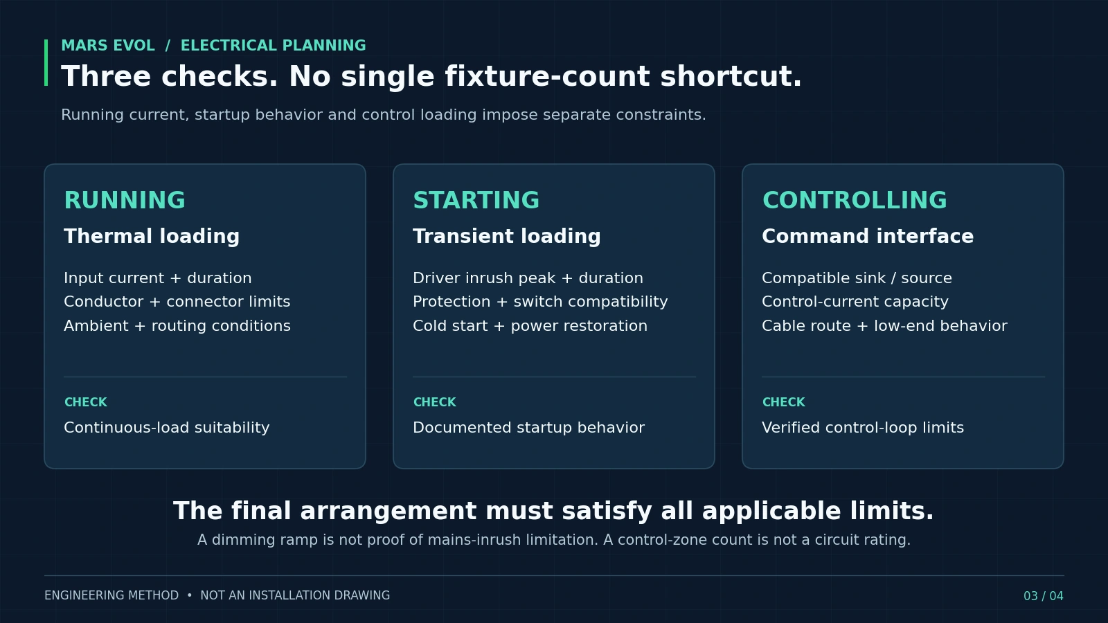
The permitted count is constrained by all relevant ratings, not just breaker amperes divided by a fixture’s running current. The electrical designer must check continuous loading, conductor ampacity, terminals, connectors, protective devices and switching equipment together.
Long greenhouse photoperiods make continuous-load review important. Schneider Electric distinguishes standard 80%-rated breakers from specifically 100%-rated designs and explains the NEC threshold: maximum current expected for three hours or more. [3] Do not assume a breaker can carry its full marked current throughout a lighting day. Apply the adopted rules and the complete equipment’s installation conditions.
Provide real cable lengths, ambient temperatures, grouping, routing and conductor information for voltage-drop and ampacity assessment. Specify acceptable voltage at the most remote fixture under load. Do not publish a universal cable gauge or maximum string length without these inputs.
Keep fault duty separate from normal operation: an interrupting rating addresses fault current, not a fixture-count allowance. OSHA explicitly requires suitable interruption capability and coordinated protective characteristics. [1] A demand-management setting also should not be credited as guaranteed capacity unless the designer and authority accept that arrangement.
5. Why Must Startup Be Checked Separately?
Electronic drivers can draw a brief charging current that is much greater than their running current. MEAN WELL describes the role of input capacitors in producing this inrush. [4] Running-power savings therefore do not prove satisfactory startup.
Request the selected driver’s inrush peak, pulse duration, test voltage and the manufacturer’s maximum-driver guidance for the proposed switching and protection devices. Ask for documented compatibility, not a generic “LED suitable” statement.
Where coordinated staged starting is proposed, confirm that the installed equipment actually supports it. Agree what happens after a brief interruption and after a prolonged outage. A normal dimming ramp is not automatically a mains-inrush limiter, especially when every driver first receives AC simultaneously.
Do not cure repeated trips by simply increasing the breaker rating. Have qualified personnel identify the cause and reassess the protected conductors, switching devices and load. Startup sequencing is a project requirement to validate, not an assumed HarveStation feature.
6. What Protection Does a Humid Greenhouse Require?
Match the whole installation to its moisture, temperature, cleaning and chemical exposure. Evaluate luminaires, remote drivers, junction boxes, connectors and cable entries individually, including their installed orientation.
UL identifies horticultural lighting as having distinctive safety considerations, including environmental exposure, ingress protection, wiring and photobiological effects. [5] Request model-specific certification evidence for the intended market; do not infer complete-luminaire approval from a certified component.
OSHA addresses suitable fixtures and receptacles in wet or damp locations. [6] An IP code alone does not establish suitability for cleaning chemicals, every washdown procedure or the entire assembled installation. Obtain the relevant equipment instructions.
The design review should cover protective grounding and bonding, applicable personnel ground-fault protection, leakage-current compatibility, surge protection and maintainable access. Preserve driver cooling and keep cables clear of moving screens and bench mechanisms. These decisions belong with the electrical designer and equipment supplier; do not bypass protective devices to keep crops illuminated.
7. How Should Electrical Circuits and Control Zones Connect?
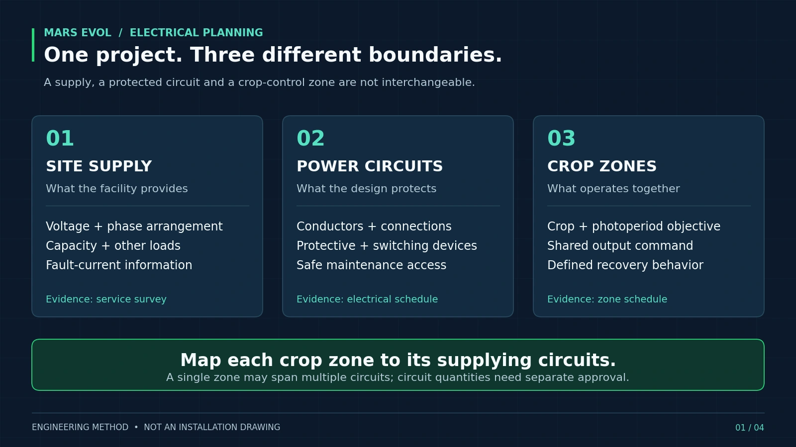
Document which protected circuits supply each crop-control zone, while keeping power and command functions distinct. A zone may contain several circuits. Its wireless device allowance does not define a breaker or cable limit.
The HarveStation system describes greenhouse partition control and daylight-responsive lighting functions. Translate that operational plan into a reviewed circuit-to-zone schedule. Use DLI-based control to define the lighting objective, not to replace protection engineering.
For an analog interface, verify sink/source compatibility, control-current capacity, permitted cable routing and low-end behavior. Lutron’s application note distinguishes these constraints from the relay’s power-circuit rating. [7] The dedicated 0–10V and zone-control guide covers the interface in more detail.
Never treat an app’s “off” command as safe isolation for maintenance. OSHA’s electrical work-practice provisions require appropriate deenergization procedures and prohibit relying only on control-circuit devices. [8]
8. What Must Commissioning Demonstrate?
Prove the installed electrical and control states against agreed acceptance criteria. Assign testing to qualified personnel using approved procedures and suitable instruments. Crop operators should not probe live panels.
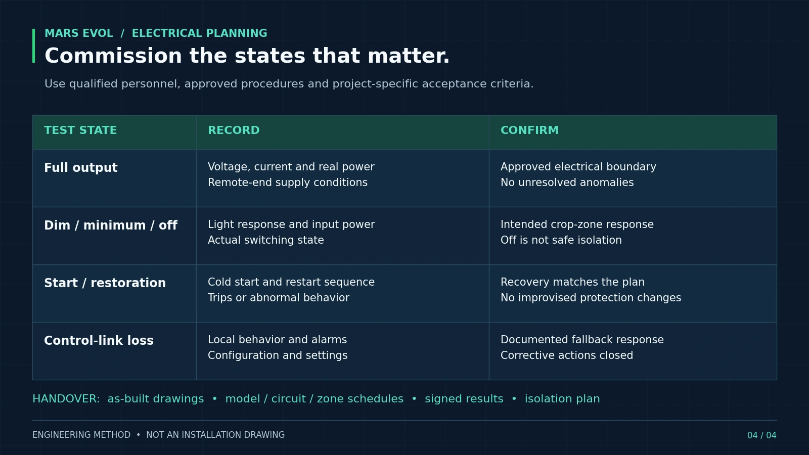
At full output, record voltage, current and real input power by the agreed circuit or zone boundary. Check the most remote fixture’s supply and retain the approved phase-loading assessment. At intermediate, minimum and off commands, record light response, power and actual switching state.
Test the approved cold-start and power-restoration sequence, together with documented communication-loss behavior. Record settings, device revisions, measurement conditions, anomalies and corrective actions. Do not create electrical faults merely to demonstrate recovery.
Handover should include as-built drawings, panel and zone schedules, equipment evidence, signed test records, maintenance instructions and an isolation plan. Freeze a configuration baseline so a replacement driver or later zone expansion triggers a compatibility review.
Common Mistakes in Greenhouse Lighting Electrical Design
- Using the product-family voltage range: confirm the exact supplied driver variant.
- Calling crop zones “circuits”: reconcile the two schedules explicitly.
- Ignoring simultaneous restart: review restoration, not only normal daytime dimming.
- Approving by an IP number: review connectors, installation and cleaning conditions too.
- Changing equipment after approval: reassess electrical and control compatibility before substitution.
FAQ
Can I size the installation from total fixture watts?
Watts establish connected real power, but not the complete electrical design. Voltage, true PF, phase allocation, continuous loading, startup, wiring and protection still need review.
Does a higher voltage reduce lighting energy use?
Not automatically. At the same input watts, higher voltage reduces current, but the luminaire still consumes the same energy for the same runtime. Distribution losses and driver performance need separate assessment.
Does “0–10V compatible” mean the lights turn fully off?
No. Confirm the selected driver’s low-end behavior and any required switching arrangement. Even genuine dim-to-off does not establish electrical isolation.
Can existing HPS wiring always be reused?
No. Its condition and ratings must be reassessed for the new drivers, protection, switching, connections and greenhouse environment. Lower steady-state watts alone are insufficient evidence.
Is UL 8800 evidence enough to approve the installation?
No. Appropriate product certification is one input. The installed electrical system, local approvals and specified use conditions still require review; certification also does not guarantee crop performance.
What should happen if a breaker trips repeatedly?
Have qualified personnel investigate before returning the affected circuit to service. Do not repeatedly reset protection, enlarge its rating or bypass it to maintain a lighting schedule.
MarsEVOL Perspective: Make the Electrical Handoff Traceable
MarsEVOL’s greenhouse approach combines fixture selection with control logic. The SOLIFY product family provides candidates for different lighting duties; the selected configuration still needs its own electrical documentation.
For greenhouse lighting electrical design, MarsEVOL recommends one coordinated package linking the fixture layout, exact model schedule, electrical interface requirements, crop zones and acceptance tests. Where web summaries and configuration documents differ, resolve the discrepancy in the approved submittal. Do not use this article’s hypothetical values as product ratings.
Conclusion
Greenhouse lighting electrical design is complete only when the supply, equipment, circuits, controls and maintenance boundaries agree. Start with verified site information, calculate transparently, check running and starting conditions separately, and commission the actual installation. A traceable handoff gives the grower, supplier and installer the same basis for decisions.
Planning a Commercial Greenhouse Lighting Installation?
Send your greenhouse drawings, fixture quantity, supply details, crop-zone plan and installer contact. MarsEVOL can help assemble lighting and control interface information for your electrical design team. Final circuit design and installation approval remain with the responsible local professionals.
Explore More MarsEVOL Resources
Define the documents and responsibilities needed before equipment is ordered.
Connect crop-light objectives with fixtures, layout and control strategy.
References
Technical sources checked September 15, 2026. The cited CFR PDFs are the July 1, 2025 edition; confirm current local applicability before design.
- U.S. Department of Labor, OSHA. 29 CFR 1910.303: General electrical requirements. U.S. Government Publishing Office, 2025.
- MEAN WELL. LED Driver FAQ: Effect of output load on power factor. Official technical FAQ, undated, Q20.
- Schneider Electric. 80%-rated versus 100%-rated circuit breakers. FAQ FA104355, updated October 14, 2024.
- Wu, W., MEAN WELL. Introduction and Selection: ICL-16 Series and Circuit Breakers. July 31, 2019; cited for the capacitor-charging explanation, not a project sizing rule.
- UL Solutions. Horticultural Lighting Testing and Certification. Official service and standards overview, undated.
- U.S. Department of Labor, OSHA. 29 CFR 1910.305: Wiring methods, components and equipment. U.S. Government Publishing Office, 2025.
- Lutron Electronics. 0–10 V Control Topology, Application Note 587. Revision J, February 2024.
- U.S. Department of Labor, OSHA. 29 CFR 1910.333: Selection and use of work practices. U.S. Government Publishing Office, 2025.