
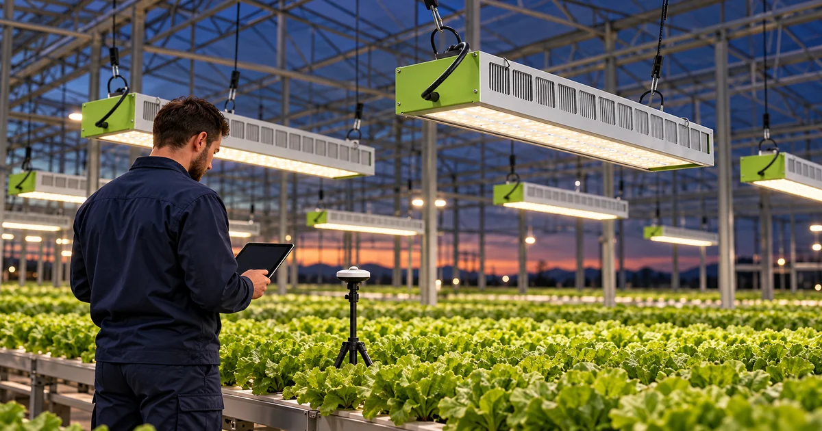
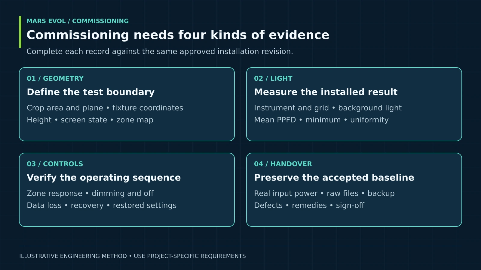
Greenhouse lighting commissioning verifies that the installed system delivers the agreed light distribution, electrical performance and control behavior. Start with a dated acceptance plan, measure electric light under repeatable conditions, test each control zone, and close defects before handover. Keep the original measurements and settings as the reference for future maintenance and troubleshooting.
Greenhouse lighting commissioning turns a purchased design into an operating record. A successful demonstration needs more than illuminated fixtures or a convincing average PPFD. The grower should be able to reproduce the measurements, identify the settings that produced them, and understand what happens when a sensor or communication link fails.
This guide addresses installed-system acceptance. Use the commercial greenhouse LED proposal evaluation guide before selecting a supplier. The methods below are MarsEVOL engineering recommendations; example thresholds and numbers are illustrative project assumptions, not universal standards or SOLIFY specifications.
Key Takeaways
- Agree on the measurement plane, crop area, operating state and acceptance rules before testing.
- Evaluate mean PPFD, distribution and power separately; one passing number does not clear the whole system.
- Test normal operation, overrides, loss of data and recovery using an approved procedure.
- Keep signed results, unresolved items and a restorable configuration together.
What should greenhouse lighting commissioning prove?
It should prove compliance with the agreed installation requirements at a documented operating condition. Crop yield remains a separate production outcome influenced by temperature, nutrition, cultivar and management. A commissioning report should not promise yield from a light measurement alone.
1. Freeze the baseline and acceptance rules
Record the final drawing revision, fixture and driver ordering codes, spectrum, quantity, mounting height, zone boundaries and controller configuration. Mark which area is productive crop space. If a proposal averages benches and aisles together while the test samples only benches, the results describe different boundaries.
Write down the required mean PPFD, the exact uniformity definition, power boundary, dimming states, permitted measurement uncertainty and the remedy for a failed test. Agree on whether borderline results require repetition or another decision rule. Do not choose tolerances after seeing the measurements.
DLC Horticultural Lighting V4.0 documents product testing, long-term performance and controllability requirements. Product qualification is useful evidence, but it does not replace acceptance of the installed greenhouse layout or its controls.[1] Identify the exact supplied configuration rather than assuming every variant in a product family shares a test result.
2. Confirm readiness and responsibilities
Name a grower representative, commissioning lead, controls specialist and qualified electrical contractor. Complete installation inspections and resolve damaged fixtures, insecure suspension or unsuitable connections before functional testing. Coordinate access around irrigation, crop handling and other equipment.
Electrical verification belongs to appropriately qualified personnel. A controller’s off command is not an isolation method for servicing; U.S. OSHA work-practice rules distinguish control devices from disconnection and lockout procedures.[5] Apply the requirements relevant to the site, with safety clearance preceding lighting performance tests.
How do you measure the installed light reliably?
Use a reproducible grid at the agreed crop plane, with a suitable calibrated quantum sensor and controlled operating conditions. Start from the PPFD mapping protocol, then preserve the coordinates so a later operator can repeat the survey.
3. Establish measurement quality
Record the sensor model, serial number, calibration date, logger scaling, spectral range and orientation. Standard PPFD covers 400–700 nm; an extended-range measurement must be labeled separately. Consult the PPFD and DLI explanation when setting reporting units.
Apogee’s SQ-500 manual identifies contamination of the diffuser as a cause of low readings and describes model-specific maintenance and calibration checks.[2] Inspect the instrument before blaming the lighting. Level it, avoid operator shadows, and keep its sensing surface at the defined height. Review permanent PAR sensor placement separately from the moving survey instrument.
Allow the system to stabilize according to the equipment and test procedure. Record ambient conditions, fixture command and elapsed time. Repeat a reference point periodically: a change there can reveal drift during the survey. Do not silently correct all other readings from a single unstable reference.
4. Separate electric light from daylight
A nighttime survey with negligible background light is usually the clearest way to compare electric-only performance. Preserve the specified screen position and greenhouse geometry because reflective surfaces can change the distribution. An opaque screen introduced only for the test can make the comparison inconsistent with the design.
If daytime subtraction is necessary, bracket a lights-on reading with lights-off readings close in time and document sunlight stability. Rapid clouds, moving shade or plant movement can invalidate the estimate. Repeat questionable measurements or use a better test window rather than presenting subtraction as exact.
Use equal-area grid cells for a simple arithmetic average. For unequal represented areas, use area weighting and document the boundaries. Include representative edges and structural shadows. Keep interlighting measurements on their defined plane; do not add lateral and horizontal readings into a fictional single-plane PPFD total.
Mean PPFD = sum of point PPFD values ÷ number of points
Minimum-to-average uniformity = minimum PPFD ÷ mean PPFD
Units for PPFD: μmol·m⁻²·s⁻¹. This uniformity ratio is dimensionless; other definitions require separate labels.
Greenhouse lighting commissioning example: mean and uniformity
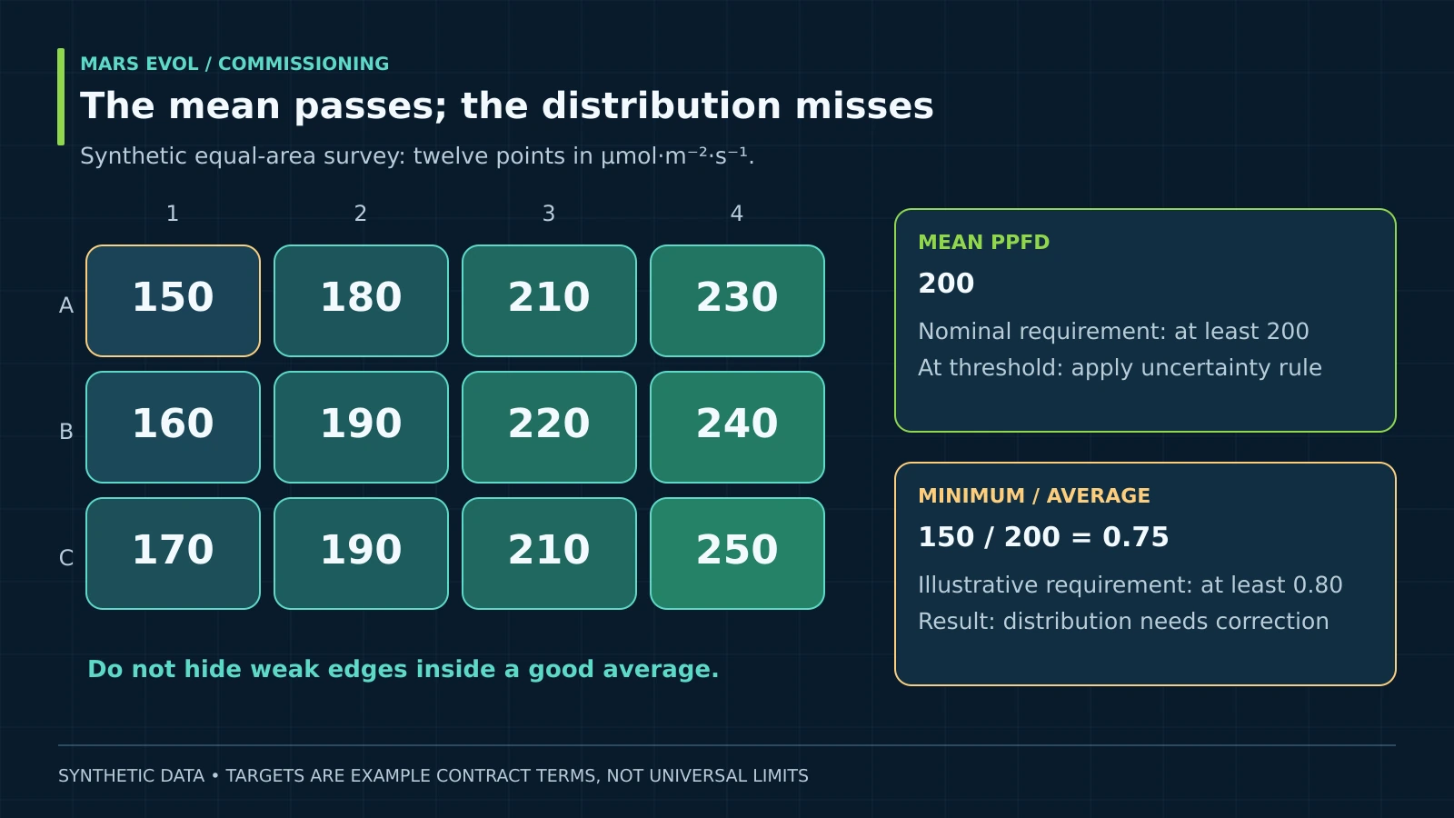
A system can meet the mean-light target while failing the agreed distribution criterion. Consider a hypothetical equal-area, twelve-point electric-only survey. Assume the project requires a mean of at least 200 μmol·m⁻²·s⁻¹ and minimum-to-average uniformity of at least 0.80, with all other test conditions held fixed.
| Grid row | Point 1 | Point 2 | Point 3 | Point 4 |
|---|---|---|---|---|
| A | 150 | 180 | 210 | 230 |
| B | 160 | 190 | 220 | 240 |
| C | 170 | 190 | 210 | 250 |
Mean = 2,400 ÷ 12 = 200 μmol·m⁻²·s⁻¹
Minimum-to-average = 150 ÷ 200 = 0.75
The mean reaches its nominal threshold; the uniformity result misses the assumed 0.80 requirement.
This is not a complete pass. Moreover, a mean exactly at the threshold is sensitive to measurement uncertainty, so apply the pre-agreed decision rule. Inspect mounting positions, shading and zone settings before proposing additional fixtures. After a correction, repeat the affected grid and check whether a neighboring area changed.
For interpretation only, operating a constant 200 μmol·m⁻²·s⁻¹ for twelve hours supplies 8.64 mol·m⁻²·d⁻¹ of electric-light DLI at that average plane. This excludes sunlight and assumes constant output. Purdue Extension explains why a daily light total requires time integration rather than one midday reading.[4]
Electric-light DLI = 200 × 12 × 3,600 ÷ 1,000,000 = 8.64 mol·m⁻²·d⁻¹
Changing dimming levels require integration over the actual operating intervals.
Which tests belong in greenhouse lighting commissioning?
Verify the entire command-to-light chain and compare measured input power at the same operating state. A working touchscreen or a correct nominal wattage does not establish installed performance.
5. Test every zone and its operating sequence
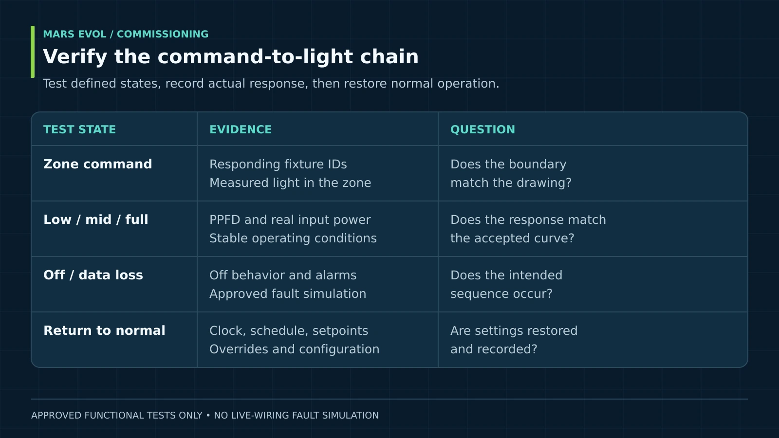
Command one zone at a time and confirm which fixtures respond. Check the approved low, intermediate and full-output states, then verify the intended off state. Record commanded output, observed response and any relevant controller feedback. A displayed percentage describes a command unless actual feedback is available.
Lutron’s 0–10 V application note explains that low-end behavior varies with the equipment and control implementation.[3] Therefore, do not assume a midrange command means exactly half the photons or half the input watts. Review the greenhouse lighting control system guide for interface planning.
| Approved test state | Observation to record | Acceptance question |
|---|---|---|
| Each zone individually | Responding fixture IDs and measured light | Does the physical boundary match the drawing? |
| Low, intermediate, full | PPFD, input power and stability | Does the installed response match the agreed curve? |
| Scheduled off | Light output and switching state | Is the required dark period preserved? |
| Approved simulated data loss | Alarm, fallback and event timestamp | Does the documented safe operating sequence occur? |
| Return to normal | Clock, schedule, setpoints and overrides | Does recovery restore the intended configuration? |
Simulate missing data through an approved software or service procedure; do not improvise by disconnecting live wiring. Test power-loss recovery only through a planned, authorized sequence. Document the selected fallback because keeping lights on, turning them off and holding the last value have different crop and energy consequences.
6. Check power and the electrical handover
Compare measured real input power with the contractual boundary: fixtures alone, fixtures plus drivers, or the complete lighting circuit. Separate unrelated loads. Record voltage and operating command alongside the measurement, and refer installation issues to the electrical contractor using the electrical planning guide.
For a hypothetical twenty-fixture zone drawing 0.62 kW per fixture at the tested state, the fixture subtotal is 12.4 kW. Add separately measured lighting-control or other included loads before assessing a whole-system limit. This arithmetic is a scope check, not a substitute for metering or a claim about a MarsEVOL model.
How should defects and handover be managed?
Close each acceptance item against its original requirement, with an owner and evidence. Greenhouse lighting commissioning remains incomplete while material defects are hidden behind a general “system operational” statement.
7. Keep a traceable defect list
For each deviation, record the location, observed value, required value, likely investigation, responsible party and due date. Distinguish safety clearance, performance correction and documentation completion. Conditional acceptance should state the remaining restriction and who can release it; it should never silently waive an unresolved safety issue.
8. Transfer a usable operating baseline
Deliver raw measurement files, grid coordinates, photos, instrument details, power readings, controller backups, zone maps and signed test sheets. Preserve the as-installed configuration before changing seasonal settings. A technician months later needs the original conditions, not just a chart without coordinates.
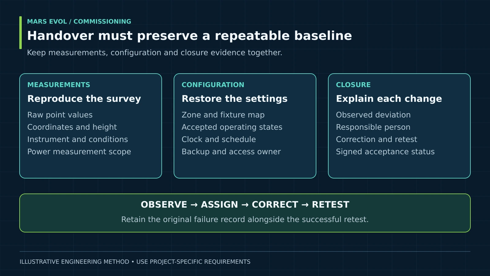
Train the grower to retrieve logs, identify active overrides, acknowledge alarms and request support. Agree who owns software access and configuration backups. Schedule a follow-up under representative production conditions when crop height, screens or operating schedules differ from initial acceptance.
Common greenhouse lighting commissioning mistakes
- Measuring beneath the brightest fixture: this misses weak edges and does not represent the crop area.
- Comparing different geometries: changed height, screens or canopy structure can invalidate the baseline.
- Counting commands as measurements: controller output percentages do not prove delivered light.
- Erasing the first result: retain the initial failure and the corrective retest to explain what changed.
Greenhouse lighting commissioning FAQ
Can commissioning be completed before planting?
Many installation and control checks can. Label the light survey as an empty-bay test, preserve its geometry, and define any production-stage follow-up. Do not assume an empty bay and a mature canopy produce identical readings.
How many PPFD points are enough?
Choose spacing that resolves fixture patterns, edges and obstacles over the agreed area. Twelve points in this article illustrate arithmetic, not a minimum grid for a commercial greenhouse. Refine the grid where gradients are large.
Must every greenhouse meet 0.80 uniformity?
No. That value is an example contractual requirement. Crop needs, measurement plane, included area and the selected uniformity definition must determine the actual target before procurement and testing.
Does a DLC listing guarantee the installed PPFD?
No. A listing concerns a product and its qualifying configuration. Geometry, mounting, obstructions, operating state and measurement method determine the installation result.
When should the system be recommissioned?
Repeat affected checks after fixture replacements, layout changes, significant control updates or unexplained performance shifts. A new baseline should identify what changed and retain the earlier record for comparison.
MarsEVOL Perspective
We recommend specifying evidence and handover responsibilities alongside the equipment order. For a project considering SOLIFY PRO, confirm the supplied fixture, driver, spectrum and control interface in the project documents. Generic examples in this guide do not establish model-specific output or an automatic commissioning service entitlement.
Conclusion
Greenhouse lighting commissioning is complete when the measured installation, tested control behavior and operating records support the agreed requirements. A repeatable baseline makes later changes easier to evaluate and gives growers a practical starting point for maintenance.
Plan the acceptance before installation
Share the layout, crop plane, fixture schedule and proposed control sequence with MarsEVOL to discuss a project-specific verification scope.
Explore More MarsEVOL Resources
Define the geometry that the acceptance survey must reproduce.
Connect the commissioned operating states with daily light management.
References
- DesignLights Consortium. Technical Requirements for LED-Based Horticultural Lighting V4.0. Revised October 1, 2025.
- Apogee Instruments. SQ-500 Quantum Sensor Owner’s Manual. Revision April 23, 2026.
- Lutron Electronics. 0–10 V Control Topology, Application Note 587. Accessed September 25, 2026.
- Torres, A. P., and Lopez, R. G. Measuring Daily Light Integral in a Greenhouse. Purdue Extension, HO-238-W, 2010.
- U.S. Occupational Safety and Health Administration. 29 CFR 1910.333: Selection and Use of Work Practices. Accessed September 25, 2026.