
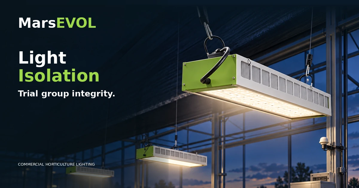
Separate experimental light-treatment zones by measuring cross-light, checking fixture geometry and documenting contamination risks before research trials. Begin by identifying measured conditions, allowed variability and the people authorized to approve changes; do not mistake a design number for a field result.
Key Takeaways
- Use the scientific experimental treatment, not a cable circuit, as the starting definition of independence.
- Document fixture configuration, measurement plane, control settings and daylight assumptions.
- Separate design calculations, actual readings and crop-response evidence.
- Set explicit acceptance methods and operating responsibilities before purchase.
- Keep traceable records and revisions as the greenhouse configuration changes.
research greenhouse light treatment isolation require more than an appropriate spectrum and a set of identical light fixtures. Researchers, growers and integrators must agree what the plant actually experiences, how it is measured and what can change without compromising the study. This guide explains the responsibilities, engineering inputs and tests that connect a commercial greenhouse lighting package to a defensible trial.
It complements the existing supplemental lighting engineering, greenhouse lighting design inputs and greenhouse bench layout resources. The focus is narrower than general luminaire selection or a whole-building PPFD map. All technical decisions below remain project-specific; no universal crop recipe, performance guarantee or unverified search-volume figure is implied.
Cross-light is a scientific design variable
Research greenhouses often allocate separate plant treatments to adjacent benches because that is operationally efficient. Unfortunately, the photons emitted by a fixture are not aware of an aisle, painted bench label or software zone boundary. Side emission, reflections and overlapping beams can introduce a background dose in the neighboring treatment. If the experimental effect being studied is small, an uncontrolled background can reduce the contrast between groups and make the interpretation of crop response harder.
Define what contamination means for the particular experiment before drawing fixtures. A propagation comparison, a spectral experiment and a photoperiod treatment study may be sensitive to different aspects of unwanted light. The decision is not whether cross-light exists at all; most shared greenhouses have some. The decision is whether its magnitude, duration and spectral contribution are compatible with the desired scientific contrast. Establish a documented acceptance threshold based on the study plan and measurement capability instead of presenting a universal isolation percentage that may not apply.
Draw treatment polygons and neighboring sources
The first engineering deliverable is a plan of actual planted treatment polygons, not simply rectangular fixture coverage. Mark the bench perimeter, growing media position, walkways, frame posts, curtains and the crop measurement plane. Include experimental replicates and locations, because a randomized block trial may move treatments through different daylight conditions. Assign every luminaire group an independent ID and identify which treatment boundaries are exposed to neighboring groups.
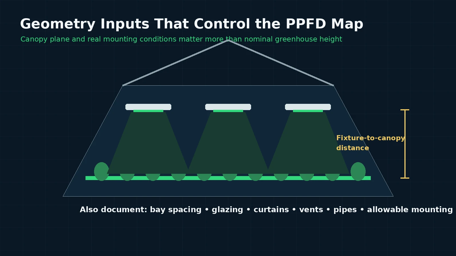
Then draw possible sources of photons entering each treatment: its own fixtures, neighboring electric groups, common background daylight and reflecting surfaces. A nominal fixture-to-canopy height and center-to-center spacing do not describe edge illumination by themselves. Model the actual optical distribution when available and label whether surrounding luminaires are included in the calculation. If only preliminary equipment data exist, describe a feasible layout hypothesis and require a commissioning measurement before claiming acceptable isolation. The project team should be able to trace each displayed region to a real group of lamps.
Choose a measurable spillover test
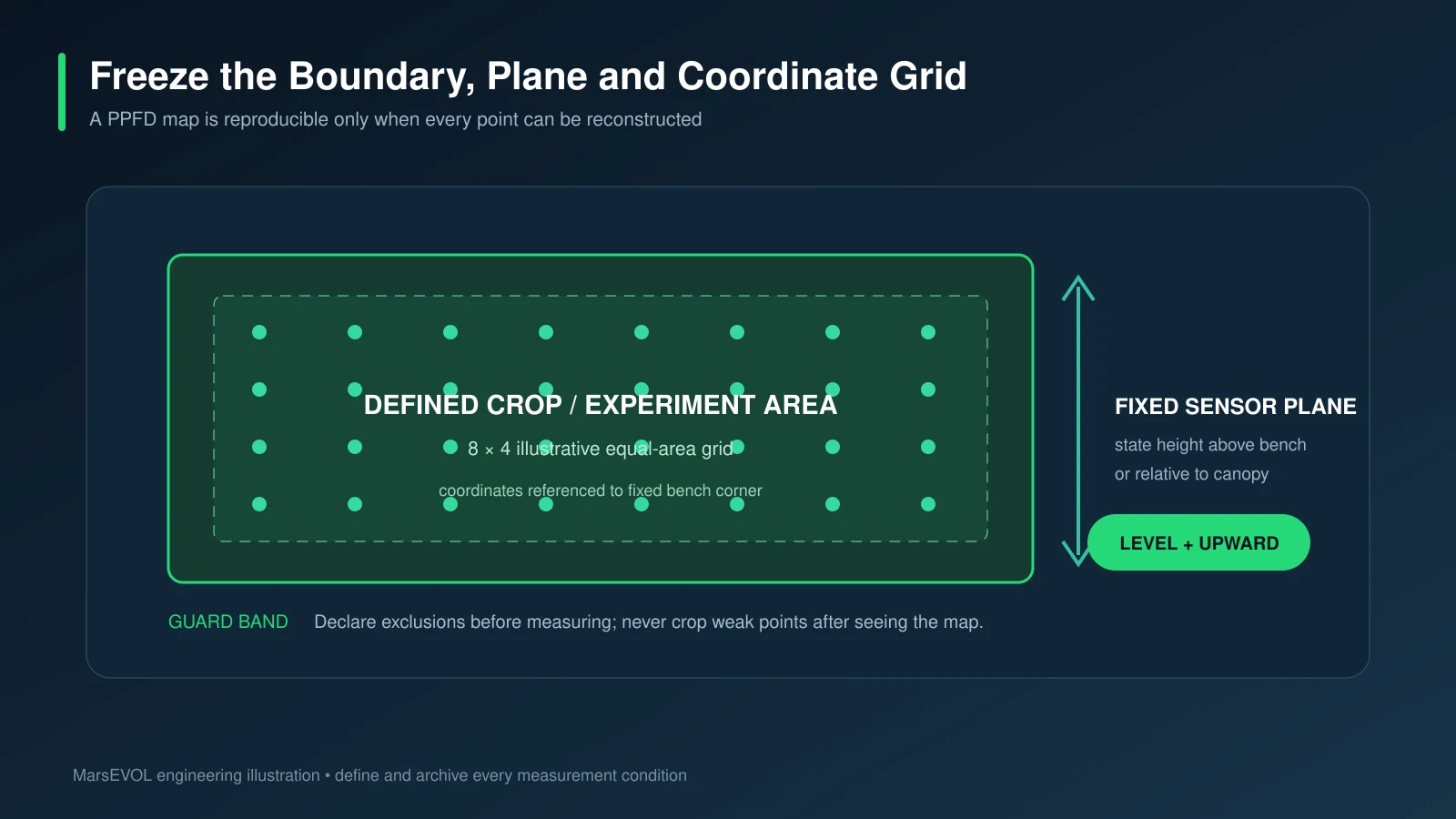
A practical method is to compare targeted measurement points with one light group on and adjacent groups off, followed by the reverse condition, where safe. Use stable settings, a calibrated PAR instrument and a consistent sensor orientation. Record a small boundary grid: the center of the treatment, several interior positions, near-edge points and points immediately across the neighbor boundary. This separates desired in-zone output from undesired neighbor contribution more meaningfully than an attractive room-wide heat map.
Control the ambient conditions while running the sequence. Ideally electric-only measurements avoid variable daylight; if testing in daylight is necessary, record the ambient baseline with a documented subtraction strategy and uncertainty. Curtains, supplemental fixtures not under test, light from a corridor and even the technician’s body can influence readings. Treat small differences near the instrument’s uncertainty as inconclusive. Repeat suspicious boundary readings rather than using one value to certify the entire experiment.
Separate intensity isolation from spectral isolation
A PAR quantum sensor measures photon flux over its response band, not the full spectral power distribution. For an experiment comparing spectra, contamination may matter even when total PPFD spillover appears modest. Far-red or ultraviolet effects, when intentionally part of a study, require wavelength-appropriate measurements and protective procedures. Do not infer spectral separation from a standard broad-band PPFD grid alone. Check the specific optical equipment and the instrumentation required by the experimental protocol.
If the experiment only compares electric-light intensity under a common spectrum, begin with the PPFD distribution and operating schedule. For different fixture spectra, document which instrument records the spectrum at crop level and how its calibration is maintained. Reflected and transmitted light may alter the delivered mix. Avoid statements that a luminaire’s label or nominal full-spectrum descriptor guarantees the treatment spectrum at the leaf. When spectral data cannot be collected, the proposed study may need a redesigned treatment layout or a more conservative interpretation.
Evaluate physical isolation without creating new risks
Possible mitigation includes changing luminaire spacing, modifying optical distribution, altering suspension height, splitting a long group, installing appropriate separation panels, or changing where treatment plots are placed. Each measure has trade-offs. A lower mounting height can reduce certain edge contributions yet increase nonuniformity within the target plot. Barriers may shade neighboring daylight, affect airflow, interfere with sprinklers or violate structural and egress constraints.
Compare mitigations in a controlled order. Change one meaningful geometry or control factor, remap the same points and preserve the original records for comparison. Do not treat a software dimming change as isolation unless the neighbor leakage test is repeated. When shielding is contemplated, coordinate with greenhouse operations and fire/electrical requirements, and assess whether the barrier creates temperature or humidity differences that confound the crop experiment. Sometimes a smaller treatment area inside a guard zone is a more defensible solution than attempting total optical separation across the whole building.
Integrate treatments with daylight and photoperiod
In supplemental greenhouse trials, sunlight provides an uncontrolled but measurable background. Roof glazing, condensation, screen deployment and structural shadow move over time. A treatment may be independent in electric-light output but not in total crop-level DLI. Decide in advance whether the study compares total photons, electric supplemental photons or a controlled difference on top of shared natural light. Use matching sensor placement or a valid correction design for those distinctions.
Photoperiod treatment studies require particular care. A neighboring group left on after the intended dark interval can contaminate a supposedly unlit treatment through even a small amount of spillover. Record switching times, astronomical or curtain constraints where applicable, and how the controller responds to a power interruption. If the desired treatment contrast cannot be maintained in a shared space, flag that limitation before the study begins; do not compensate by silently altering control recipes after the researcher has collected partial results.
Run a commissioning matrix for all combinations
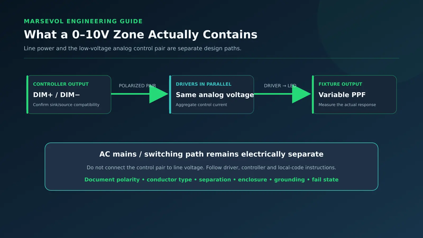
A robust isolation acceptance test works through more than a single all-lights-on map. At minimum, test each treatment group individually, representative paired groups, and the planned normal operating combination. Verify that electrical and software identifiers match the physical fixtures. Record driver level, measured PPFD at the same grid points, neighboring contributions, sensor conditions, and any fixture relocation. A dedicated technician and researcher should jointly confirm that the test reflects the scientific requirements.
Include conditions likely to reveal hidden coupling: one group at the minimum permitted level, a neighboring group at full expected output, a scheduled transition and a manual override. Check that a communication loss or reset cannot leave a sensitive plot illuminated outside its approved period. The resulting matrix becomes an operational control document, not only a commissioning appendix. It allows the next trial team to check whether changes in crops, furniture, lighting or building systems have invalidated the original treatment separation.
Make the experimental claim proportional to the evidence
Supplier and investigator reports should distinguish simulated leakage, field-measured leakage and the assumptions used to judge it. Report measurement coordinates, the instrument, the calibration status, fixture levels, environmental conditions and timing. Include the difference between target and neighbor readings where useful, and explain whether the method can resolve the observed difference. Avoid implying that one site-specific result proves the same performance in another greenhouse geometry.
For a commercial research supplier, the useful offer is a repeatable verification service: annotated treatment plan, control group matrix, boundary-grid measurements, recommended mitigation and a witnessed retest. The report should explain any residual uncertainty and give the investigator enough information to decide whether to adjust treatment assignment or data analysis. That approach supports scientific credibility more effectively than promising that independent software zones automatically eliminate every influence from adjacent fixtures.
Calculation and evidence boundaries
This equation is an integration example, not a universal crop target. When output varies through the day, calculate the time series integral. Record whether readings include daylight and which canopy plane they represent.
Common mistakes
Common errors include copying fixture quantities from a greenhouse of different height, comparing bench-center readings while excluding the edges, assuming a percent dimming command represents measured photons, or confusing a grower’s crop objective with a verified installation output. Another mistake is to report a scientific treatment as perfectly independent without measuring neighbor spillover and the natural-light background. Correct these problems in the design and acceptance plan rather than with unsupported marketing claims.
Data provenance matters as much as arithmetic. Keep names and units stable; retain the equipment and instrument identification; and link the timing of control changes to the timing of biological sampling. For broader commissioning context, use PPFD field mapping, lighting schedule optimization and PPFD proposal validation. The same procedure can later help troubleshoot a pilot bench before scaling a commercial array.
FAQ
Can software zones alone prevent cross-light?
No. Software changes electrical commands but cannot prevent photons from neighboring fixtures crossing a physical boundary. Optical layout or measured mitigation is needed.
How should cross-light be reported?
Record neighbor-only PPFD at the prescribed crop-level grid along with sensor, timing, spectrum assumptions and the configuration of each fixture group.
Does an aisle between benches create optical isolation?
Not necessarily. Beam overlap can cross open spaces, especially near edges or with high mounting. The actual site geometry and photometry matter.
Can one PPFD map verify all experimental states?
No. At least representative single-group and planned combined-group states should be tested, including sensitive operating transitions.
Should we block all stray light with partitions?
Only after assessing airflow, irrigation, crop access, shading, structural loads and safety. A guard zone or different placement may be preferable.
Why consider spectrum if the project specifies PPFD?
Experiments that intentionally compare spectral treatments may be affected by wavelength-specific leakage that a broad-band quantum sensor cannot distinguish.
Conclusion
Research light-treatment isolation is not a decorative line between zones. It is an experimentally testable condition that combines optical geometry, control sequencing, instrument quality and a predetermined interpretation threshold. A disciplined boundary test protects both project investment and research validity.
Build a Project-Specific Lighting Plan
Send the experimental treatment plan, bench polygons, fixture geometry, measured daylight conditions and the scientific contrast you need to preserve between treatment groups.
Explore More MarsEVOL Resources
Review how bench geometry and fixture-to-canopy distance shape the starting distribution.
Use a repeatable field grid to distinguish predicted distributions from observed boundary contributions.
References
- Cornell Controlled Environment Agriculture. Cornell Controlled Environment Agriculture — official resources. Controlled-environment production and research education.
- Michigan State University Floriculture. Michigan State University Floriculture — official resources. University extension resources relevant to greenhouse environments.
- Illuminating Engineering Society. Illuminating Engineering Society — official resources. Professional lighting measurements, guidance and standards.